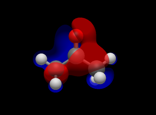
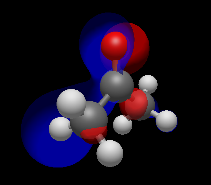
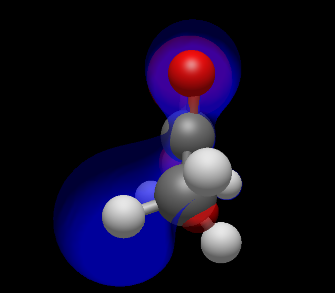
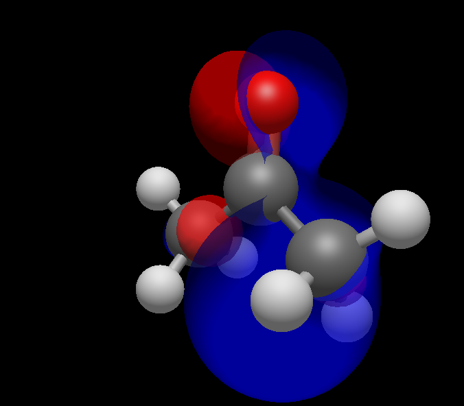
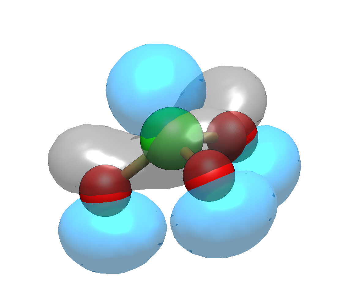
I think I have a fix for the visual artifacts with translucent orbital rendering:
The issue happens because the translucent surfaces “add up” along a particular viewing angle.
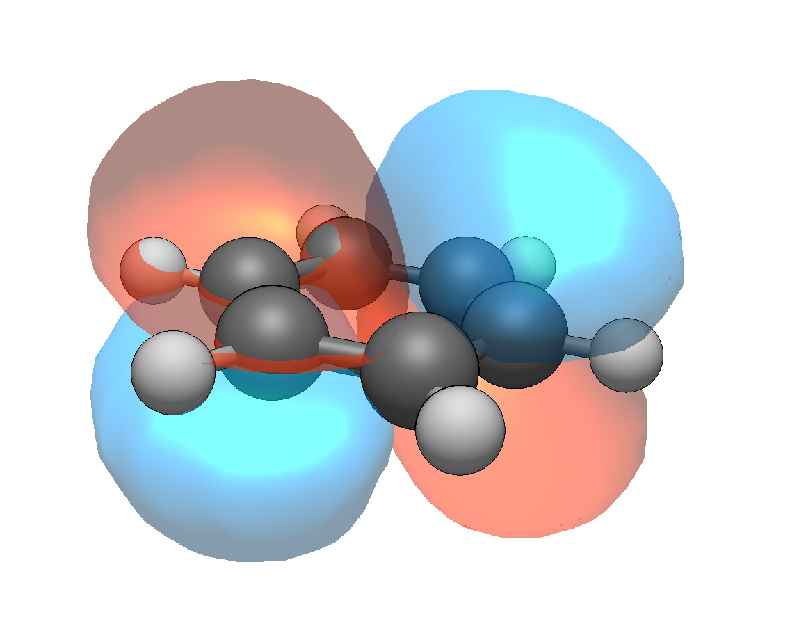
I’ll do a bit more testing, but so far it looks good.
I think I have a fix for the visual artifacts with translucent orbital rendering:
The issue happens because the translucent surfaces “add up” along a particular viewing angle.
I’ll do a bit more testing, but so far it looks good.
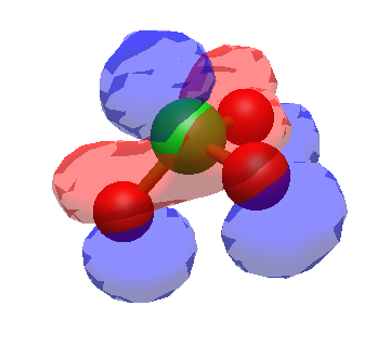
Sometimes the surfaces yield “windows” both to front and back side, though (to someone who relays quantumchemical computations to whose in the know) apparently there is sufficient volume around the molecules enclosed. Below, an observation with Avogadro 1.100.0-7-gac3rf38r in Windows 10.
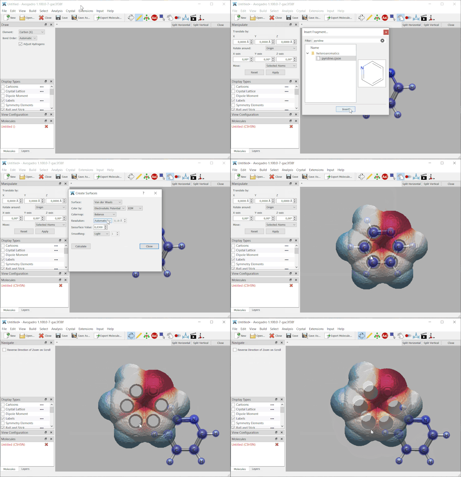
There’s definitely a separate bug there - that once you move the molecule, the surface should be invalid.
But it looks like for the VdW surfaces, we need to add a bit more padding. Basically, when you create any kind of surface (orbital, etc.) we generate a “cube” data structure for tracking the value of f(x,y,z) at points in space.
The current code then generates a mesh based on the isosurface of particular values (e.g., the VdW surface in your example). But if the cube didn’t enclose all the points .. you get gaps like that. (It comes up with some diffuse orbitals too.)
That should be a fairly easy fix.
The surfaces now look the same from all angles, which is great, and the result looks very nice!
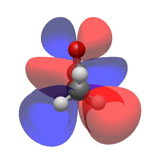
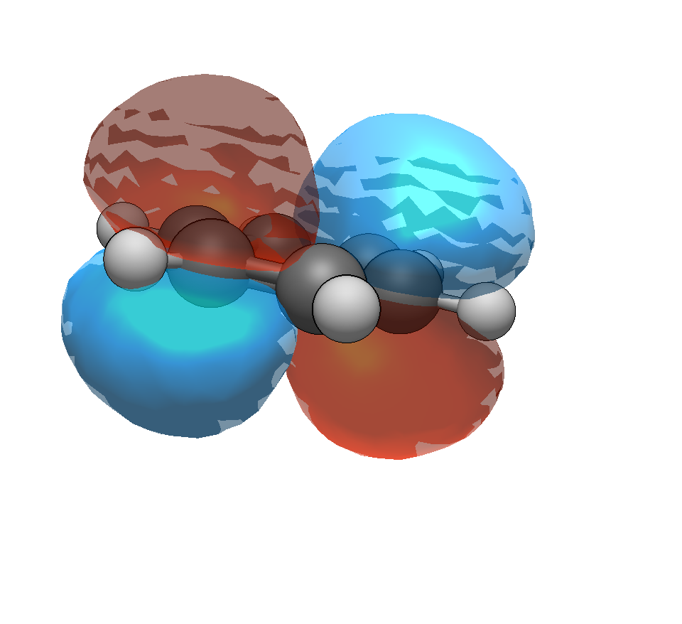
For me though, I now see the slightly odd behaviour shown in the image below:
It looks like when looking at orbital surfaces with the color2 colour, here the default blue, only the interior face of the surface is visible, not the exterior. Hence the atoms not being tinted blue.
These other angles help to make this obvious – look at the way the orbital vanishes on the left of the carbonyl carbon:
The red phases on the other hand seem to render correctly.
The different behaviour of the two phases also seems to be apparent from the way that they seem to be lit/shaded inversely (presumably because you are seeing the convex red surface and the concave blue surface):
It makes it look like the red phase is being lit from above (i.e. matching the atoms) while the blue phase appears to be being lit from below.
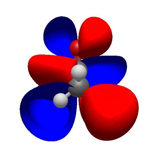
There is also a peculiar jump from 99% opacity:
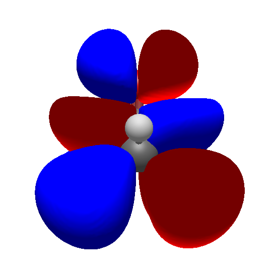
to 100%:
The exterior surface of the blue phase is suddenly rendered, but the lighting directions are suddenly inverted. They are inverted for both phases, with the result that they are still inconsistent between the phases, but now it’s the red phase that is wrong…
Yes, there’s a difference in the “winding” of the triangles between + and - phases as far as lighting. But that hasn’t changed in the last few months.
Well, the bug was introduced as a result of your other bug fix in March, and @callumhind was using “1.98 or 1.99 or 1.100” previously, all of which pre-date that.
Can confirm that this issue is not present with the wireframe style (colours are vibrant and lighting is good). Seems like it’s isolated to the surface style on my end at least.
I’ve downgraded to v1.99.0 and the rendering is back to how it was previously. So it may be a bug in a subsequent version.
If it would help, I can attempt to pinpoint the version where the changes occur, if that would be of any help to you?
Sure - certainly knowing when the bug changed helps to narrow down the revisions.
I’m going to look into a few things this evening.
As I mentioned in another thread this is now fixed:
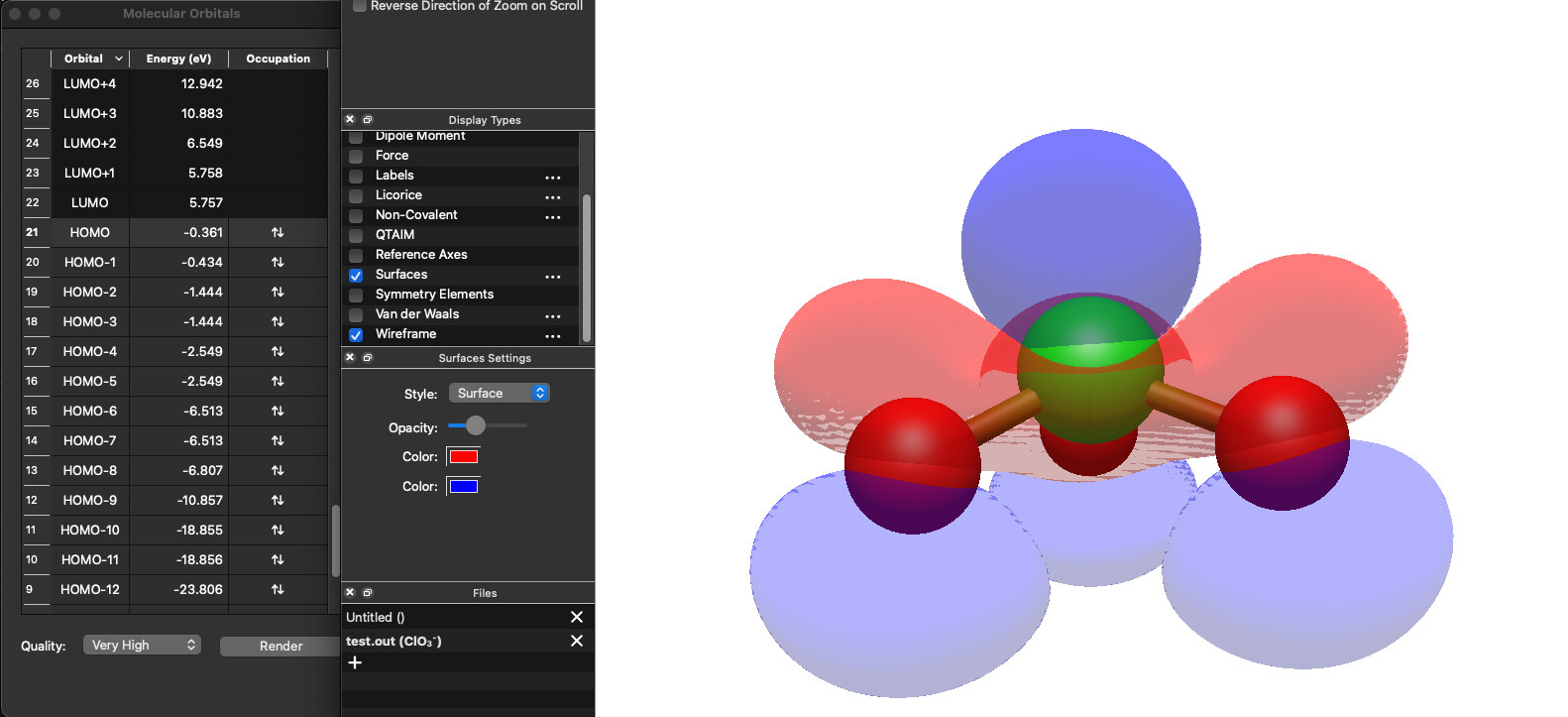
I am still seeing the initial bug reported in this thread on an apple silicone version.(not sure if that matters in this case)
I’ve attached the orca output file I am viewing as well.
test.out (668.6 KB)
It would help significantly to know what version you’re using. But there’s only so much I can do as a non-render expert.
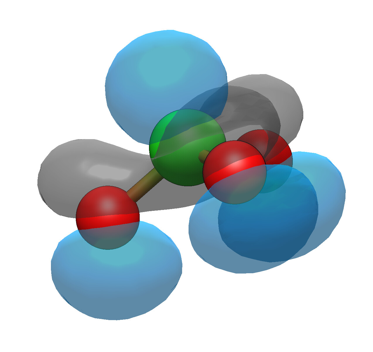
For me, it can still show up sometimes depending on the specific camera angle, but it’s less of a problem with higher resolution surfaces:
The above and included frames are from the nightly release render. But I was seeing the same in the stable release.
As I said, what you’re describing is different from this particular thread. It’s somewhat inherent in having multiple translucent triangles in the mesh and as a non-expert at OpenGL rendering, I’m not sure what else I can do to change it. We don’t do full ray-tracing for performance reasons.
Appreciate it. I’ll play around with some code on my end.
The appropriate files would be the various mesh* code here:
My guess is there could be some tweaks to the fragment shader:
I’ll see if Claude or ChatGPT has some suggestion to tweak this.